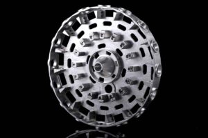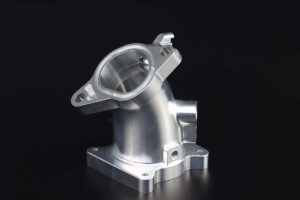
5-axis CNC machining for robot end-effector housings can consolidate angled tool interfaces, cable passages, pneumatic ports, sensor mounts, locating faces, and weight-reduction pockets into fewer controlled setups. Robot integrators, gripper manufacturers, automation builders, and production engineering teams should send more than a STEP file when requesting a quotation. A useful RFQ states robot model, payload, tool-center-point envelope, loads, duty cycle, collision assumptions, material, datum scheme, interface standards, tolerances, surface treatment, quantity, and delivery milestones. Those inputs let the machining supplier plan stock, fixtures, cutting sequence, inspection, finishing masks, assembly checks, and a credible route from prototype to repeat production.
Best-Fit Applications and Practical Limits
The process is well suited to compact wrist adapters, gripper bodies, vacuum tooling frames, camera and sensor brackets, quick-change plates, welding-tool housings, and multi-sided manifolds whose functional features must remain aligned. Five-axis access can reduce refixturing and protect the relationship between the robot flange, tool datum, dowel holes, ports, and working face. It is not automatically the economical choice for flat plates, simple turned adapters, welded frames, or very high volumes that justify castings or extrusions. Buyers should compare feature access, tolerance stack, mass target, annual demand, qualification cost, and alternative constructions before specifying a process on every component.
Define Loads, Interfaces, and Safety Assumptions
Provide the robot flange standard, bolt circle, dowel pattern, fastener grade, tool mounting interface, payload, center of gravity, static and dynamic loads, acceleration, emergency-stop loads, expected collisions, and any guarding or safety function. Identify pneumatic, vacuum, electrical, coolant, and data connections, including connector clocking and service access. The housing supplier can machine to a controlled definition but should not be expected to infer the complete structural or machine-safety design. State whether calculations, material allowables, proof loading, fatigue review, or a customer-approved design are required. Freeze responsibility for the robot adapter, purchased inserts, fasteners, and downstream tooling before production release.
Control Datums, Tolerances, and Tool-Center Position
A ballooned drawing should identify the primary robot interface, tool datum, locating bores, dowel holes, sealing faces, threaded ports, sensor targets, and any surfaces that determine tool-center position. Use functional geometric tolerances instead of applying unnecessarily tight general limits. Clarify whether dimensions apply before or after anodizing, nickel plating, conversion coating, paint, or other treatment. Where interchangeable tooling is required, define the master gauge or measurement method and acceptable repeatability. Thin walls, long bores, interrupted cuts, and deep pockets can move during machining, so agree on free-state inspection, restraint, stabilization, stock allowance, and the sequence used to protect critical relationships.
Choose Material and a Weight-Reduction Strategy
Aluminum alloys are common where low moving mass and short robot settling time matter, but the exact alloy, temper, stock form, grain direction, certificate, and corrosion environment must be specified. Steel or stainless steel can suit compact high-load interfaces, while engineering polymers or hybrid structures may suit lighter duties. Do not remove material without considering stiffness, fastener pullout, bearing surfaces, cable protection, cleaning, and collision loads. A DFM review can compare pocket geometry, ribs, wall thickness, radii, inserts, and access for cutters and probes. The approved model should retain enough material for stable machining and repeat assembly rather than chasing the smallest possible mass in isolation.
Plan Machining, Inserts, and Surface Treatment
The route may include roughing, intermediate measurement, stress redistribution, finish machining, deburring, tapping, insert installation, cleaning, coating, marking, and final inspection. Define thread standards, helicoil or key-lock insert type, installation depth, torque checks, prohibited burrs, edge breaks, and areas that must remain electrically conductive. Coating notes should state process, color, thickness, masked bores, threads, sealing lands, and dimensional acceptance after treatment. If vacuum passages or manifolds are included, identify plugged cross-drillings, allowable sealants, leak-test pressure, cleanliness, and port labeling. Approved samples should represent the intended material, machining route, insert source, finish supplier, and inspection method.
Inspect Functional Relationships, Not Only Dimensions
Inspection should follow the end-effector's assembly and robot-calibration risks. A CMM report can cover flange flatness, datum position, dowel spacing, port locations, bore alignment, and working-face orientation. Thread gauges, surface-roughness checks, coating thickness, mass, leak testing, proof loading, or a fit fixture may also be required. The report should identify drawing revision, material lot, part serial or batch, inspection equipment, and disposition. For interchangeable tools, use the same master or gauge concept across prototypes and production. Buyers should define first-article scope, sampling frequency, capability evidence, and how deviations are reviewed before an urgent cell build is affected.
Build a Quote Package for Prototype and Series Supply
Send native or neutral CAD, a controlled PDF drawing, interface standards, loads, material and finish, inserts, inspection and documentation needs, prototype quantity, annual forecast, release pattern, destination, and target delivery. Separate mandatory requirements from supplier-proposed improvements. Ask the quotation to show material, programming or non-recurring engineering, fixtures, inserts, finishing, inspection, packaging, and freight assumptions. Prototype approval should verify fit, tool-center relationship, stiffness, routing, finish, handling, and service access. After approval, freeze the revision, program, fixture, finish route, inspection plan, packaging, and change-control procedure so repeat housings remain interchangeable across robot cells.
Procurement Comparison
| Review area | Buyer input | Acceptance evidence |
|---|---|---|
| Interfaces | Robot flange, tool datum, ports, connectors | Ballooned drawing and fit fixture |
| Loads | Payload, center of gravity, duty, collisions | Approved design assumptions |
| Construction | Alloy, inserts, finish, mass target | Material and process records |
| Supply | Prototype, forecast, release, delivery | Frozen route and change control |
Frequently Asked Questions
What files should accompany a robot housing RFQ?
Provide 3D CAD, a revision-controlled 2D drawing, robot and tool interface standards, functional datums, loads, material, finish, inserts, inspection needs, quantity, forecast, destination, and schedule. Include pneumatic, vacuum, electrical, coolant, and sensor connections, plus any approved calculation or master-gauge requirement.
When does five-axis machining reduce project risk?
It helps when angled and multi-face features must maintain close positional relationships or when fewer setups protect the robot flange, tool datum, ports, and sensor mounts. It may add little value to simple plates or turned adapters. A DFM review should compare process options against tolerance, volume, and qualification needs.
How should tool-center-point accuracy be specified?
Define the datum structure, relevant faces and bores, geometric tolerances, inspection condition, temperature if important, and the approved measurement method. If tools must be interchangeable, supply a master, gauge, or calibration procedure. Do not rely on a general drawing tolerance to control the complete assembled tool-center relationship.
Should threaded inserts be installed by the machining supplier?
They can be, when the insert brand, part number, hole preparation, installation depth, orientation, locking method, torque or proof check, and replacement rule are defined. Clarify whether inspection occurs before or after coating and who supplies special inserts. Include representative inserts in prototype and first-article approval.
How can repeat end-effector housings remain interchangeable?
Approve a production-equivalent first article, then freeze CAD and drawing revision, stock specification, machining program, fixture, insert source, finish route, inspection method, master gauge, markings, and packaging. Require documented review before any substitution or process change, and link inspection and material records to each production batch.
Image Suggestions
- Five-axis machining of a lightweight robot wrist housing — alt: 5-axis CNC machining robot end-effector housing
- CMM inspection of robot flange and tool datums — alt: robot end-effector housing datum inspection
- Anodized housings with installed inserts in protective trays — alt: finished robot end-effector housings for assembly
Internal Links and Next Step
Review the related product and capability information, then use the official project contact page to send specifications for an engineering review and quotation.
Lead Qualification Questions
- What is the exact application, operating environment, and project country?
- Which model, drawing, material, size, or performance requirements apply?
- What quantity, forecast, samples, testing, and documentation are needed?
- What packaging, labeling, certification, destination, and delivery date apply?
- Who will approve the technical specification and first article?
Request a B2B Project Quotation
Send the application, technical data, required quantity, project schedule, destination, drawings or photos, testing and documentation needs, and purchasing contact. The team can then review suitability, identify missing inputs, and prepare a project-specific response. This guide supports industrial projects, distributors, contractors, system integrators, and OEM or ODM programs rather than one-piece retail purchasing.