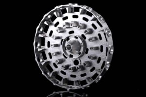
5-axis CNC machining impeller prototypes gives pump developers a practical way to evaluate blade geometry, hub interfaces, balance strategy, assembly fit, and test-rig performance before production tooling or a larger machining release. Pump OEMs, skid builders, laboratory teams, and rotating-equipment engineers should provide the fluid, duty range, speed, rotation, CAD, controlled drawing, material, surface condition, balance requirement, inspection plan, prototype quantity, test purpose, and revision schedule. The machining supplier can then review tool access, blade thickness, workholding, stock condition, distortion, metrology, handling, and delivery as one controlled prototype route without claiming that machining alone validates the final hydraulic design.
Freeze the Test Objective and Hydraulic Inputs
Explain whether the prototype will be used for dimensional fit, a dry assembly, water testing, a representative process liquid, cavitation observation, efficiency development, vibration work, or endurance trials. State normal and extreme flow, head, speed, pressure, temperature, density, viscosity, solids, gas content, suction condition, rotation, drive power, and test duration. Mark the operating points that matter and identify which party owns the hydraulic design and system safety. A geometry that is adequate for a short visual trial may not be approved for pressure, temperature, corrosion, fatigue, or long-duration service. Link each prototype revision to a defined question and measurable acceptance result so test feedback can guide the next design rather than producing uncontrolled CAD changes.
Control Blade Geometry, Datums, and Interfaces
Provide native 3D CAD plus a controlled 2D drawing that identifies revision, units, rotation, inlet and outlet features, blade count, leading and trailing edges, hub bore, keyway or spline, threads, sealing faces, shaft interface, nut direction, balance features, and assembly datums. Distinguish functional surfaces from reference dimensions and define tolerances only where fit, clearance, flow, sealing, or measurement requires them. Thin twisted blades, deep channels, undercuts, and narrow passages can limit cutter diameter, reach, approach angle, and inspection access. Ask for a manufacturability review before freezing the model. If the impeller mates with a diffuser, volute, wear ring, shaft, or cover, provide those interface dimensions and required running clearances together.
Specify Material, Stock Condition, and Traceability
Name the alloy or engineering polymer, grade, condition or temper, stock form, material standard, and certificate level. Explain whether the prototype material must represent production corrosion, strength, density, temperature, magnetic, or balance behavior, or whether a substitute is allowed for an early geometry trial. Stock condition affects residual stress, dimensional movement, cutting strategy, and availability. Identify prohibited substitutions and any heat treatment, stress relief, passivation, anodizing, plating, coating, or polishing requirement. The complete fluid-wetted construction may also include a shaft, fastener, insert, coating, adhesive, seal, and nearby metal, so a material certificate for the impeller alone does not establish chemical compatibility. Maintain lot identity through machining, inspection, test preparation, and shipment.
Plan Workholding and Thin-Feature Machining
Agree on the starting stock, roughing sequence, intermediate support, rest periods if needed, finish allowance, tool access, deburring, and final release method. Impeller prototypes can combine interrupted cuts, changing tool engagement, long-reach tools, and thin blades that are vulnerable to deflection or handling damage. The machining plan should protect the functional datums and hub interface while maintaining access to each blade surface. Temporary tabs, sacrificial stock, soft jaws, custom fixtures, or staged operations may be proposed, but removal and witness-mark limits should be approved. If additive or cast preforms are being compared with billet machining, keep the routes and acceptance evidence separate rather than assuming identical material structure or finishing behavior.
Define Surface Finish, Edge Condition, and Balance
Identify where surface texture affects sealing, fit, fatigue, flow development, fouling, or test repeatability, and specify the measurement direction and method. Define edge-break limits, burr acceptance, leading and trailing edge protection, blend areas, polishing boundaries, coating allowance, and surfaces that must not be reworked. Balance requirements need the applicable method or standard, service speed, correction planes, arbor or mounting condition, key convention, allowable correction locations, and report format. A balance result is meaningful only when the test setup matches the agreed assembly state. State whether balance occurs before or after coating and whether later test drilling, grinding, or repair requires rebalancing. Protect delicate edges and balance features during cleaning and packing.
Build a Metrology and Test Evidence Package
Use a risk-based inspection plan that matches the prototype question. It may include material certification, hub and interface dimensions, datum establishment, blade-profile comparison, scanning or CMM results, surface texture, runout, mass, balance records, visual inspection, and photographs. Define the CAD comparison alignment and the permitted reporting format before inspection begins. Features hidden between blades may require optical, probe, replica, or section-based methods, so do not request an impossible conventional measurement after machining. Record instrument identity, calibration status, inspection temperature, support condition, and revision. The pump developer should separately document assembly clearances, test-rig configuration, flow, head, power, vibration, and other hydraulic results because those outcomes are not established by the dimensional report alone.
Move from Prototype Revisions to Repeat Supply
Release the smallest prototype batch that can answer the planned questions, while preserving enough units for dimensional confirmation, rig testing, destructive examination if required, and reference retention. After each test, classify findings as hydraulic design, interface, material, machining, balance, assembly, controls, or test-rig issues. Update CAD, drawings, inspection characteristics, and the change log together. Before pilot supply, freeze material, stock form, tool access assumptions, fixtures, programs, balance procedure, approved rework, cleaning, marking, packaging, and documents. Commercial comparison should include engineering review, fixtures, programming, inspection, balance, certificates, revision loops, test support, packaging, forecast, and delivery risk rather than only a prototype unit price.
Procurement Comparison
| Review area | Buyer input | Acceptance evidence |
|---|---|---|
| Test objective | Duty, fluid, speed, revision question | Approved test plan and limits |
| Geometry | CAD, blades, hub, datums, clearances | FAI and profile comparison |
| Rotating quality | Runout, edge condition, balance setup | Inspection and balance report |
| Revision control | Prototype quantity, change log, pilot freeze | Released drawing and route |
Frequently Asked Questions
What files should be included with an impeller prototype RFQ?
Send native 3D CAD, a controlled 2D drawing, revision, rotation, fluid and duty data, speed, material and stock condition, blade and hub interfaces, tolerances, surface and edge requirements, balance method, inspection characteristics, prototype quantity, test purpose, destination, and schedule. Include mating-part or clearance data where the impeller interfaces with a shaft, diffuser, wear ring, cover, or volute.
Can a machined prototype prove production pump performance?
It can support controlled development, but it does not by itself prove final performance or production equivalence. Hydraulic results depend on the complete pump, system curve, fluid, clearances, speed, surface condition, assembly, instrumentation, and test method. Production material, casting or forming route, heat treatment, coating, balance, and dimensional variation may differ, so define what each prototype test is intended to validate.
How are twisted impeller blades inspected?
The method depends on access, tolerance, surface, and the required evidence. Options may include CMM probing, optical scanning, profile measurement, dedicated fixtures, or CAD comparison with a defined alignment. Hidden areas can be difficult to reach. Agree on critical sections, datum strategy, point density, reporting format, temperature, support, and acceptable uncertainty before machining and inspection begin.
When should the impeller be balanced?
Define whether balance is required for the current test and specify the method or standard, service speed, mounting condition, key convention, correction planes, allowable correction areas, and report. Balance normally follows the agreed final machining and surface state. If coating, test modification, repair, or material removal changes mass distribution, the buyer should define whether rebalancing and a new record are required.
How should prototype revisions be controlled?
Give every CAD model, drawing, inspection plan, balance instruction, and test result a clear revision. Record the reason for each change and the test question it addresses. Do not mix geometry from one revision with a report from another. Before pilot production, freeze the released definition, approved sample, material, route, fixture, inspection, balance, cleaning, marking, packaging, and change-approval process.
Image Suggestions
- Five-axis machining of a pump impeller prototype — alt: 5-axis CNC machining impeller prototypes
- Impeller blade profile inspection against released CAD — alt: CNC impeller prototype blade inspection
- Prototype impeller mounted for documented balance verification — alt: pump impeller prototype balance test
Internal Links and Next Step
Review the related product and capability information, then use the official project contact page to send specifications for an engineering review and quotation.
Lead Qualification Questions
- What is the exact application, operating environment, and project country?
- Which model, drawing, material, size, or performance requirements apply?
- What quantity, forecast, samples, testing, and documentation are needed?
- What packaging, labeling, certification, destination, and delivery date apply?
- Who will approve the technical specification and first article?
Request a B2B Project Quotation
Send the application, technical data, required quantity, project schedule, destination, drawings or photos, testing and documentation needs, and purchasing contact. The team can then review suitability, identify missing inputs, and prepare a project-specific response. This guide supports industrial projects, distributors, contractors, system integrators, and OEM or ODM programs rather than one-piece retail purchasing.