Analysis of Skills to Improve Machining Accuracy of Five-axis Machining Center
Analysis of Skills to Improve Machining Accuracy of Five-axis Machining Center
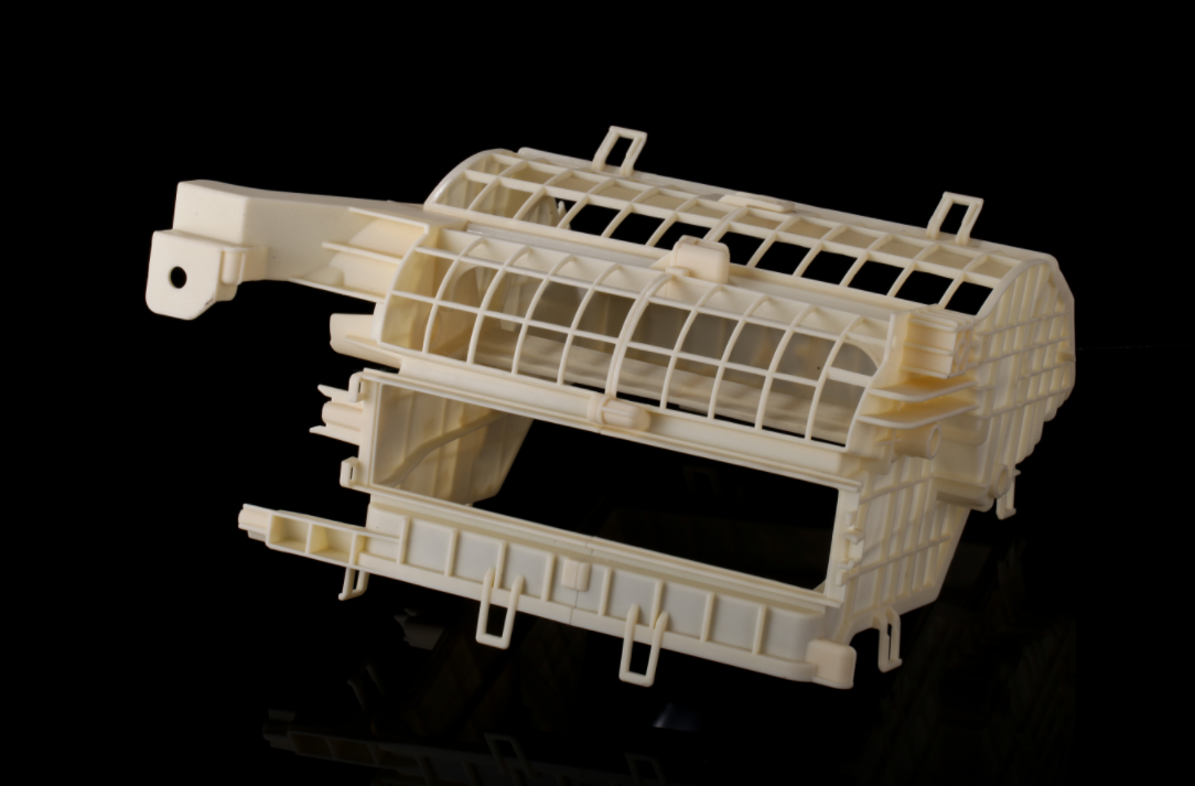
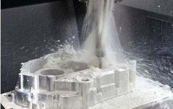
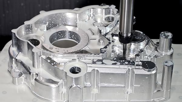
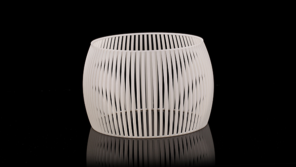
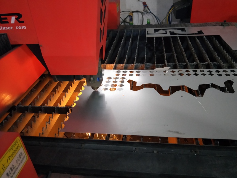
Some die products whose geometrical features is circumferentially distributed relative to the center of the workpiece are relatively simple in appearance, but their geometric accuracy requirements are very high. As the processing quantity of mold products is usually produced in single piece and small batch, the trial-production-correction-production mode cannot be adopted to eliminate the processing error and make the products meet the precision requirements. Especially for large-sized and high-priced die products, it is necessary to consider how to reduce the machine tool error before processing to improve the processing dimensional accuracy. Fig. 1 shows a part of automobile mold made of steel with hardness of HRC30. Due to the high tolerance requirements of machining elements' dimensions and positions, the production personnel have adopted various methods to reduce errors and improve accuracy.

Fig. 1 die structure diagram
1. Analysis of parts processing difficulties
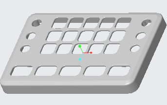
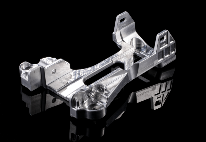
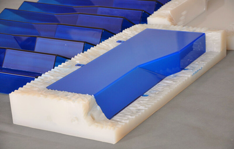
There are three main processing difficulties of this part. Difficulty 1: The symmetry of two symmetrical 80mm×65.6mm inclined boxes relative to the center of the part is 0.03 mm. Difficulties: The width of the inclined frame is 18 ~ (80 0.01) mm, which makes it difficult to process and measure. Difficulty 3: There is an R3 spatial arc connection between two adjacent inclined planes (see Figure 2), which needs to solve the machining problem.
Fig. 2 Partial view of mold
2. Solutions to difficulties
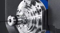
According to the precision requirements of parts, the machine tool processed by the five-axis machining center [1] has the structure of swinging head and rotary table. Because the dynamic error of the five-axis machining center machine tool is affected by the temperature change of the machine tool and the error of the rotary center of linkage machining, it is very difficult to ensure the symmetry within 0.03 mm. In view of this situation, two methods are used to reduce the error. One is to install the blank after turning in the rotating center of the workbench, and the spindle is used to install the dial indicator and the workbench rotates to knock the center of the workpiece to coincide with the rotating center of the workbench. The other is the bevel finishing program, in which one bevel is edited manually, and the other 17 bevels are repeatedly processed by modifying the offset of coordinate C axis. The advantage of this method is that it eliminates the error between the actual turning center of the machine tool and the numerical value of the turning center stored in the machine tool for calculation. However, it is necessary to manually modify the C-axis offset for 17 times after machining a surface, which obviously can't make the machining coherent, and there is a risk that the modification error will lead to scrapping. Through research, this problem is solved by automatically modifying the C-axis offset by the machine tool after reading the macro instruction of numerical editing. Specific finishing procedures are as follows:
The circular function program used in finishing is simple and clear, and the dimensional error can be easily corrected by modifying cutter compensation.
2. The difficulty in machining and measuring the width of the inclined frame is 18 ~ (80 0.01) mm. Two methods are adopted to solve the problem: one is to separate the rough and finish machining processes; the other is to increase the measurement size after the trial cutting of the cutter compensation and then correct the cutter compensation when finishing the first frame. Because the depth of the step surface is shallow, the infrared probe is used to edit the measurement program during measurement, and the numerical value is measured on the machine tool to correct the cutter compensation. When the size of the first frame reaches the precision requirement, when machining the second frame, it is necessary to fully consider the size change caused by the change of allowance due to no longer trial cutting. Generally speaking, the duller the tool, the harder the material and the greater the dimensional change.
Between two adjacent inclined planes, the machining of R3 spatial arc cannot be edited by manual programming. The R3 arc combination software here adopts the method of five-axis linkage local machining, but the connection with the machined straight lines on both sides also needs the method of trial cutting and correction, so that the machining effect is the best.
3. Actual processing effect
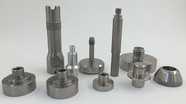
By installing the workpiece in the rotary center to correct the C-axis offset, combining with the manual programming method to reduce the influence of the rotary center error on the position degree, and using the method of knife compensation correction combined with infrared probe measurement, the dimensional accuracy can meet the drawing requirements. After the workpiece is processed, the geometric tolerance and dimensional tolerance measured by three coordinates meet the drawing accuracy requirements.
4. Conclusion.
When machining high-precision single-piece die parts with five-axis machine tools, it is necessary to comprehensively consider the machine tool precision, alignment method, programming method, dimension correction and other aspects before machining, so as to eliminate errors and improve machining accuracy. All details are well considered, which can effectively improve the accuracy and reduce the scrap rate of workpieces. In addition, the combination of manual programming and software programming can improve the machining accuracy of this kind of parts with uniform circumferential shape.