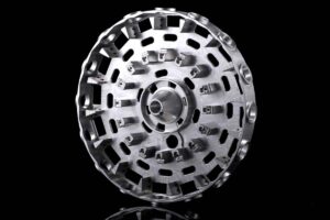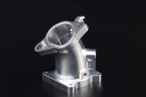
CNC machining aluminum LiDAR housings for test units requires coordinated control of optical alignment, sensor and PCB interfaces, thermal paths, sealing, cable exits, external datums, surface treatment, and prototype revision. LiDAR developers, autonomous-system integrators, robotics companies, metrology teams, and equipment OEMs should provide released CAD, a controlled drawing, optical and mechanical interface data, alloy, environment, finish, inspection characteristics, test quantity, and schedule. A machining supplier can then review datum logic, thin-wall distortion, tool access, workholding, burr control, masking, cleanliness, metrology, and packaging without claiming that the empty housing alone validates ranging performance or final environmental compliance.
Define the Test Unit and Functional Interfaces
Explain whether the housing supports a bench prototype, vehicle test, robot integration, calibration fixture, environmental trial, or pilot assembly. Identify the laser, receiver, optics, window, PCB, connector, heat source, mount, gasket, fastener, and cable interfaces, including ownership of each mating component. State field of view, keep-out zones, permissible obscuration, service access, shock and vibration inputs, temperature range, ingress target, expected duty, and whether the unit will be opened repeatedly during development. Separate requirements that belong to the machined housing from optical calibration, electronics, firmware, sealing validation, and complete-system safety. Link every prototype revision to a defined test question and measurable acceptance result.
Freeze Datums, Optical Alignment, and Stack-Up
Provide native 3D CAD and a controlled 2D drawing with revision, units, material, finish, datum scheme, critical dimensions, geometric tolerances, threads, inserts, sealing surfaces, window seat, sensor and PCB locations, and vehicle or fixture mounts. Define which surfaces establish the optical axis and how the housing is restrained during assembly and inspection. Use a stack-up that includes machined parts, window, gasket, adhesive, insert, PCB, sensor carrier, fasteners, coating, and temperature effects. Do not apply unusually tight tolerances to every surface. Mark only characteristics that influence alignment, focus, seal compression, connector engagement, heat transfer, assembly clearance, or calibration repeatability, then agree on the inspection method before machining.
Select Alloy, Stock, and Material Traceability
Name the aluminum alloy, temper, stock form, material standard, certificate level, and permitted source. Billet, plate, extrusion, casting, and near-net stock can differ in residual stress, porosity, grain direction, availability, finish response, and dimensional movement. State whether the test unit must represent the intended production route or whether a billet prototype is acceptable for geometry learning. Identify prohibited substitutions and any thermal-conductivity, mass, corrosion, magnetic, vacuum, or cleanliness constraint. Maintain lot and revision identity from incoming stock through roughing, finish machining, treatment, inspection, cleaning, and packing. A material certificate confirms identity but does not prove the finished assembly's optical, thermal, sealing, or environmental performance.
Control Thin Walls, Heat Paths, and Workholding
Review wall thickness, ribs, bosses, deep pockets, connector cutouts, window openings, heat-spreader areas, undercuts, internal channels, and tool access before release. Asymmetric stock removal and thin sections can move after unclamping or surface treatment. The route may require staged roughing, controlled support, rest periods, soft jaws, sacrificial features, balanced stock removal, and a defined final setup on functional datums. Protect flat thermal interfaces and sealing faces from clamp damage. If a thermal pad or conductive adhesive will be used, specify the required flatness, texture, and coating mask. Agree on allowable witness marks, tab removal, edge breaks, and rework so prototype parts remain comparable across revisions.
Specify Finish, Masking, Sealing, and EMC Features
Define anodizing, conversion coating, paint, plating, passivation, blasting, polishing, or another treatment by an applicable specification, class, color, thickness, and approved sample where appearance matters. Identify masking on threads, gasket lands, electrical bonding points, thermal contacts, window seats, and precision bores. Coating thickness can change fits and seal compression, while aggressive blasting can alter edges or flatness. If conductive contact or shielding is required, show the complete grounding and fastening concept rather than requesting generic EMI protection. Name the gasket material, groove dimensions, compression target, adhesive boundaries, venting, drain strategy, and leak-test responsibility. Confirm chemical compatibility for cleaners, sealants, and the final use environment.
Build Inspection, Cleanliness, and Assembly Evidence
Use a risk-based inspection plan covering material identity, dimensions, datum setup, optical interfaces, connector and PCB positions, sealing surfaces, flatness, threads, inserts, finish, masking, burrs, and visual condition. CMM, optical measurement, calibrated gauges, surface-texture instruments, scan comparison, and functional fixtures may be combined according to access and tolerance. Define inspection temperature, support condition, reporting format, sample size, and measurement uncertainty. Internal chips, sharp edges, residue, and loose media can threaten optics and electronics, so specify cleaning, inspection lighting, bagging, caps, separators, and particle or residue evidence where needed. The system owner should separately document optical alignment, thermal, vibration, ingress, EMC, and calibration results.
Move from Prototype Learning to Repeat Supply
Order the smallest controlled batch that supports dimensional confirmation, assembly, calibration, environmental work, destructive checks if required, and reference retention. After testing, classify findings as optical design, electronics, thermal, sealing, housing geometry, machining, finish, assembly, software, or test-method issues. Update CAD, drawings, inspection characteristics, bills of material, and change records together. Before pilot supply, freeze alloy and stock, fixtures, programs, inserts, finish and masking, cleaning, inspection, approved rework, marking, packaging, and supplier-change approval. Compare quotations on engineering review, tooling, machining, treatment, inspection, documents, revision loops, yield, packaging, forecast, and delivery risk rather than prototype unit price alone.
Procurement Comparison
| Review area | Buyer input | Acceptance evidence |
|---|---|---|
| Optical interface | Axis, window, sensor, keep-outs | Stack-up and interface report |
| Mechanical route | Alloy, walls, datums, workholding | First article dimensional report |
| Surface system | Finish, masking, seal and bonding | Approved visual and treatment record |
| Prototype release | Quantity, test plan, revisions | Signed sample and change log |
Frequently Asked Questions
What files should be sent for a LiDAR housing quotation?
Send native 3D CAD, a controlled 2D drawing, revision, alloy and stock requirement, optical and mechanical interface data, mating-part details, critical tolerances, finish and masking, sealing concept, thermal contacts, inserts, inspection characteristics, prototype quantity, test purpose, packaging, destination, and schedule. Identify any confidential geometry and the required NDA process before transferring controlled files.
Can a machined housing prove final LiDAR performance?
No. It can provide controlled geometry for development, but ranging performance also depends on optics, emitters, receivers, electronics, firmware, window, alignment, calibration, thermal behavior, vibration, contamination, sealing, and test methods. Define exactly what the housing prototype is intended to verify and keep complete-system validation with the responsible engineering team.
How should optical datums be inspected?
Agree on functional datums, restraint, inspection temperature, features that represent the optical axis, permitted uncertainty, and report format. Depending on access and tolerance, the supplier may use CMM, optical measurement, gauges, scan comparison, or an assembly fixture. Inspection must reproduce the agreed reference condition instead of measuring an unsupported thin housing arbitrarily.
Should anodizing be applied before final inspection?
The sequence depends on which dimensions are controlled in the treated state and which areas are masked. Coating can alter bore size, threads, seal compression, electrical contact, and surface texture. Define the final-state drawing, masking, thickness, post-treatment checks, and any dimensional allowance before machining. Retain treatment certificates and a visual standard when color matters.
How can prototype revisions remain traceable?
Give each CAD model, drawing, inspection plan, treatment instruction, assembly record, and test result a matching revision. Mark parts or packages with an approved non-damaging method and record material lot, process route, and shipment. Do not combine one revision's part with another revision's report. Freeze the accepted configuration before pilot or repeat supply.
Image Suggestions
- Five-axis machining of an aluminum LiDAR housing — alt: CNC machining aluminum LiDAR housings
- Optical and connector datum inspection on a LiDAR enclosure — alt: LiDAR housing datum and interface inspection
- Masked anodized LiDAR housings in protective packaging — alt: anodized LiDAR test unit housings
Internal Links and Next Step
Review the related product and capability information, then use the official project contact page to send specifications for an engineering review and quotation.
Lead Qualification Questions
- What is the exact application, operating environment, and project country?
- Which model, drawing, material, size, or performance requirements apply?
- What quantity, forecast, samples, testing, and documentation are needed?
- What packaging, labeling, certification, destination, and delivery date apply?
- Who will approve the technical specification and first article?
Request a B2B Project Quotation
Send the application, technical data, required quantity, project schedule, destination, drawings or photos, testing and documentation needs, and purchasing contact. The team can then review suitability, identify missing inputs, and prepare a project-specific response. This guide supports industrial projects, distributors, contractors, system integrators, and OEM or ODM programs rather than one-piece retail purchasing.