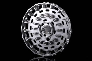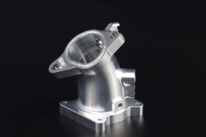
5-axis CNC machining satellite camera housings helps consolidate angled optical interfaces, sealed connector faces, heat-transfer features, mounting datums, and weight-reduction pockets into controlled setups. Aerospace, Earth-observation, robotics, and optical-instrument buyers should not request a quote from a 3D model alone. The supplier needs a controlled drawing, alloy and temper, datum scheme, optical-axis relationship, mass target, thermal path, surface finish, cleanliness level, inspection plan, quantity, and program schedule. Those inputs determine stock form, workholding, machining sequence, stress relief, deburring, dimensional verification, finishing masks, packaging, and the practical route from prototype housings to repeat flight or ground-support production.
Best Applications and Important Limits
This process can suit compact camera bodies, gimbal frames, optical benches, sensor mounts, star-tracker enclosures, lens-barrel interfaces, connector panels, and thermally managed electronics housings with features on several faces. It is especially useful when setup consolidation protects positional relationships between bores, sealing planes, mounting feet, and optical datums. It is not automatically the lowest-cost route for simple prismatic boxes, very large cast structures, or volumes that justify a dedicated forging, extrusion, or die-cast tool. Buyers should compare geometry, tolerance stack, annual quantity, qualification burden, and material removal before deciding that five-axis work is necessary for every feature.
Freeze Datums, Optical Interfaces, and Tolerances
The drawing should identify primary mounting planes, optical centerlines, bearing or lens seats, connector clocking, sealing grooves, thread standards, flatness, position, runout, and surface-finish requirements. Separate functional tolerances from general dimensions so inspection effort follows risk. Clarify whether dimensions apply before or after anodizing, plating, conversion coating, or paint, and define mask areas. Thin walls and deep pockets can move after roughing or finishing, so a DFM review should address stock allowance, machining sequence, intermediate stabilization, fixture access, probe strategy, and the free-state or restrained condition used for inspection.
Select Alloy, Stock, and Thermal Features
Aluminum alloys are common for mass and thermal reasons, but the exact alloy, temper, plate or billet specification, grain direction, certification, and ultrasonic or other material evidence should match program needs. Magnesium, titanium, stainless steel, copper inserts, and engineering polymers may suit different structures but change machining, corrosion, joining, mass, and supply risk. Define heat-source locations, interface materials, thermal pads, inserts, venting, and allowable temperature gradient. Where fins, heat pipes, threaded inserts, or bonded components are involved, provide the assembly method and loads rather than expecting the machining vendor to infer the complete thermal design.
Control Thin Walls, Burrs, and Surface Finishing
Weight targets often create thin ribs, interrupted walls, deep cavities, and narrow sealing lands. Stable workholding, balanced material removal, sharp tools, chip evacuation, controlled heat, and protected finishing passes reduce distortion and surface damage. Burrs around cross holes, threads, vents, and cable paths can contaminate optics or interfere with assembly. Define edge breaks and prohibited rounding on sealing or locating features. For anodizing, conversion coating, electroless nickel, paint, passivation, or black optical finishes, specify the governing process, color or reflectance need, thickness, masked regions, contact areas, adhesion evidence, and post-finish dimensional acceptance.
Build Inspection Around Functional Relationships
Inspection may combine CMM programs, calibrated bore gauges, optical measurement, surface-roughness testing, thread gauges, flatness checks, coating thickness, mass, leak testing, and assembly fixtures. A useful report ties characteristics to drawing balloons and records the revision, material lot, machine or fixture route, inspection equipment, and disposition. Optical-axis relationships may need a dedicated gauge or customer-supplied master rather than only standard coordinates. Agree on first-article scope, sample rate, capability evidence, and how the supplier handles deviations. For recurring orders, lock the approved program, fixture, inspection method, and finish source under change control.
Plan Prototype, Qualification, and Production Lots
A prototype lot should answer fit, optical alignment, thermal contact, sealing, cable routing, finish, handling, and assembly questions before qualification. The next stage can validate repeat workholding, dimensional capability, finish consistency, packaging, and documentation on production-equivalent material. Buyers should share expected annual volume and release pattern so the supplier can plan stock, tooling, inspection time, and capacity. Commercial comparison should include material certificates, machining, inserts, finishing, inspection, cleaning, special packaging, non-recurring engineering, and freight. Send revision-controlled CAD and drawings with a change log to prevent an obsolete housing from entering production.
Procurement Comparison
| Review area | Buyer input | Acceptance evidence |
|---|---|---|
| Geometry | Optical datums, sealing planes, thin walls | Ballooned drawing and CMM report |
| Material | Alloy, temper, stock route, traceability | Certificate linked to finished lot |
| Finish | Coating, masks, thickness, reflectance | Approved sample and finish record |
| Program | Prototype, qualification, annual demand | Frozen revision and change control |
Frequently Asked Questions
What files are needed for a satellite housing quote?
Provide native or neutral 3D CAD, a controlled 2D drawing, datum and tolerance scheme, exact material, finish and mask notes, inserts, cleanliness and packaging requirements, annual quantity, first-article expectations, and delivery milestones. Identify optical, sealing, thermal, and interface characteristics that require special inspection or a customer master.
When is five-axis machining justified?
It is justified when angled or multi-face features must hold close relationships, fewer setups materially reduce stack error, or access is difficult with three-axis methods. Simple faces may still use conventional operations. A supplier should review the complete part and propose the lowest-risk process instead of applying five-axis machining as a marketing label.
How are thin aluminum housing walls controlled?
The plan can use stable stock, balanced roughing, staged material removal, suitable fixtures, controlled cutting heat, intermediate measurement, and finishing passes after stress has redistributed. The drawing should state inspection condition and functional datums. Extremely thin features may need a design adjustment, temporary support, or a different manufacturing route.
Should tolerances apply before or after coating?
State this explicitly for every affected feature. Coating thickness can alter bores, threads, sealing lands, electrical contacts, and mating faces. Drawings should identify masks and post-finish dimensions, while the purchase order should define the process standard, color or optical requirement, thickness evidence, and approved finishing source.
How should buyers qualify a repeat supplier?
Approve a production-equivalent first article covering material, machining, inserts, finish, dimensions, cleanliness, markings, and packaging. Review nonconformance control, calibration, traceability, change management, and capacity. Then freeze the accepted drawing, program, fixture, inspection method, finish route, and packaging revision for subsequent lots.
Image Suggestions
- Five-axis machining of a lightweight optical housing — alt: 5-axis CNC machining satellite camera housing
- CMM inspection of optical and mounting datums — alt: satellite camera housing dimensional inspection
- Finished black-coated camera housings in protective trays — alt: machined satellite camera housings protective packaging
Internal Links and Next Step
Review the related product and capability information, then use the official project contact page to send specifications for an engineering review and quotation.
Lead Qualification Questions
- What is the exact application, operating environment, and project country?
- Which model, drawing, material, size, or performance requirements apply?
- What quantity, forecast, samples, testing, and documentation are needed?
- What packaging, labeling, certification, destination, and delivery date apply?
- Who will approve the technical specification and first article?
Request a B2B Project Quotation
Send the application, technical data, required quantity, project schedule, destination, drawings or photos, testing and documentation needs, and purchasing contact. The team can then review suitability, identify missing inputs, and prepare a project-specific response. This guide supports industrial projects, distributors, contractors, system integrators, and OEM or ODM programs rather than one-piece retail purchasing.