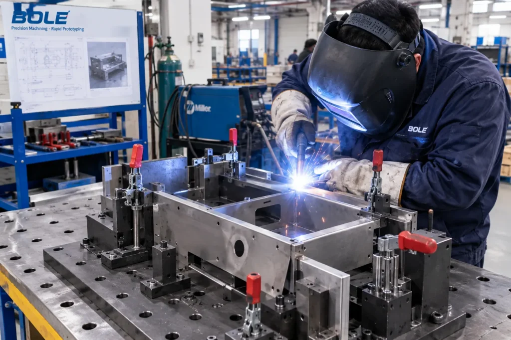
— BOLE Precision Sheet Metal Fabrication Solutions
Welding distortion is a common challenge in the production of sheet-metal assemblies such as enclosures, frames, and equipment housings. It directly affects dimensional accuracy, assembly fit, and appearance. Drawing on practical manufacturing experience, BOLE Precision Machining explains the causes and typical forms of welding distortion and shares practical process-control measures to help customers reduce rework and ensure the quality of custom sheet-metal parts.
In precision sheet-metal manufacturing, welding is a key process for assembling components such as enclosures, equipment frames, brackets, panels, and metal housings. Welding joins multiple sheet-metal parts into an integrated assembly with specified strength and functionality. However, the localized high temperatures generated during welding can easily cause warping, angular distortion, dimensional shrinkage, and residual stress within the part.
For thin-walled sheet metal and precision assemblies in particular, even slight welding distortion can cause assembly interference, hole-position shifts, out-of-flatness, and cosmetic defects. In severe cases, the part may have to be scrapped.
BOLE provides end-to-end manufacturing services for CNC machining, rapid prototyping, and custom sheet metal. Our project experience shows that distortion is often not caused by welding operations alone; it can result from multiple factors involving product design, fixtures, process parameters, and the transfer of parts between operations. Understanding the mechanism and controlling the process in advance is far more efficient than relying on post-weld correction. This article explains the causes of sheet-metal welding distortion and presents practical control measures for production.
1. Key Causes of Sheet Metal Welding Distortion
Core principle: uneven heat input. During welding, a highly concentrated, high-temperature heat source (an arc or laser) acts on a localized area of metal for a short time. The weld and nearby metal heat up and expand rapidly, then contract as they cool. This uneven thermal expansion and contraction is the root cause of sheet-metal welding distortion. The amount of distortion also depends on material properties, sheet thickness, joint design, welding parameters, and fixture restraint.
(1) Thermal Stress Caused by Localized Heating and Cooling
This is the primary cause of welding distortion.
Heating Stage: During welding, the metal in and around the weld (the heat-affected zone, or HAZ) is rapidly heated and tends to expand freely. However, this expansion is strongly restrained by the surrounding cooler base metal, which is at a lower temperature and provides resistance to deformation. As a result, the heated metal is subjected to compressive stress and may undergo localized plastic deformation.
Cooling stage: Once the heat source moves away, the area begins to cool and contract. Because it was compressed during heating, it tends to contract more than it would under free contraction. The surrounding cooling metal restrains this excessive contraction, creating residual tensile stress in the weld area, balanced by compressive stress in the surrounding region.
Result: When the balance between tensile and compressive stresses exceeds the material’s yield strength, the component warps, bends, or twists to release some of the stress. This is the distortion we observe.
A simple analogy: Imagine a row of people standing tightly together (representing metal atoms). Several people in the middle suddenly become very hot and try to expand, but those on either side prevent them from doing so, squeezing them together (plastic compression). Then they cool suddenly and try to shrink further. Because they were compressed earlier, they pull the people on either side inward as they contract. Eventually, the whole row bends.
(2) Transverse and Longitudinal Shrinkage
Transverse shrinkage: Contraction perpendicular to the weld direction. It reduces the width of the sheet metal component near the weld and may cause angular distortion, particularly in V-groove butt welds, where the root side of the joint may open.
Longitudinal shrinkage: Contraction along the weld direction. It shortens the overall workpiece and may cause longitudinal bowing.
(3) Angular Distortion
In V-groove butt welds or fillet welds, the weld cross-section is often asymmetrical, resulting in uneven heat input and cooling across the joint. This causes differential thermal contraction, with the greater contraction on one side producing angular distortion. Similar to heating only one side of a hinge, the uneven contraction causes the workpiece to rotate or bend.
(4) Buckling (Instability Distortion)
Thin sheet metal is particularly susceptible to buckling due to its limited resistance to compressive instability. Residual compressive stresses generated during welding can cause localized loss of stability, resulting in wave-like bulges or depressions. This type of deformation is known as buckling or instability distortion.
Once it occurs, this type of distortion can be very difficult to correct. Therefore, it is important to minimize the risk through preventive process planning and appropriate welding controls.
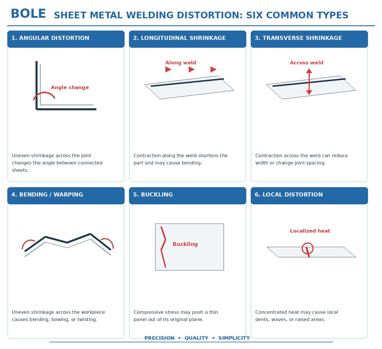
Six Common Types of Sheet Metal Welding Distortion
In production, distortion rarely occurs in only one form; several types often overlap. The welding distortion most frequently encountered in BOLE’s workshop includes:
| Distortion Type | Typical Characteristics and Possible Effects |
|---|---|
| Angular distortion | Uneven shrinkage on either side of the joint or through the sheet thickness changes the angle at the connection. Common in corner joints and welded assemblies. |
| Longitudinal shrinkage | Contraction along the length of the weld reduces the overall length after welding. |
| Transverse shrinkage | Contraction perpendicular to the weld may change the gap between joint edges or the dimensions of the assembly. |
| Bending and warping | Uneven shrinkage in different areas causes panel bending, bowing, or twisting. |
| Buckling | When compressive stress exceeds a thin panel’s resistance to buckling, the panel may move out of its original plane. |
| Local distortion | Concentrated heat in a small area may cause dents, surface waviness, or local lifting near the weld. |
(6) Why Are Thin Sheet-Metal Parts Especially Prone to Distortion?
Low stiffness: Compared with heavy castings and forgings, sheet-metal parts are usually only a few millimeters thick. Their stiffness and resistance to deformation are low, so even a small amount of internal stress can cause visible distortion.
Limited restraint: Sheet-metal structures are often relatively open and provide little restraint against distortion, allowing stress to be released more freely through deformation.
High thermal conductivity: Metals such as steel and aluminum conduct heat well. Heat spreads quickly from the weld into the surrounding material, creating a relatively large heat-affected zone. A wider area of metal therefore experiences uneven thermal cycling, increasing the area affected by distortion.
Note: Thin sheet metal does not inevitably suffer severe distortion. Through design optimization, process-parameter adjustment, and custom fixtures, BOLE has achieved controlled welding dimensions on many thin-walled enclosure products.
(7) Other Key Production Factors That Can Increase Welding Distortion
Welding distortion is not just an issue at the welding station. Upstream operations, materials, and fixtures all affect the final condition of the product:
- Material properties: Different steels and aluminum alloys have different coefficients of thermal expansion and yield strengths, so their distortion behavior varies significantly. Controlling distortion in thin aluminum sheet is generally more challenging than in ordinary carbon steel.
- Joint design: Butt, lap, corner, and T-joints have different shrinkage behavior and stress-concentration characteristics.
- Welding parameters: Current, voltage, travel speed, and the number of weld passes directly affect the extent of the heat-affected zone.
- Welding sequence: An unsuitable sequence allows shrinkage forces to accumulate in one direction, increasing bending and twisting.
- Clamping and fixtures: If a fixture only clamps the part without allowing appropriate movement, dimensions may appear acceptable during welding but spring back and distort after the fixture is released.
- Upstream process accuracy: Deviations from laser cutting and bending carry over into welding and can magnify assembly and welding errors.
2. Seven Practical Ways to Control Welding Distortion in BOLE’s Sheet Metal Workshop
Welding distortion is difficult to eliminate completely, but early design review, process control, and suitable fixtures can keep it within drawing tolerances. Prevention should take priority; post-weld correction should not be the only control method.
(1) Optimize Welding Parameters and Precisely Control Heat Input
Heat input is a key variable in distortion. Greater heat input creates a wider heat-affected zone and more pronounced expansion and contraction. BOLE process engineers select current, voltage, and travel speed according to the material, sheet thickness, and joint type. Excessive heat input is avoided while ensuring adequate penetration and weld strength.
Where strength requirements allow, intermittent welding is preferred over continuous welding to reduce total heat input. However, parameters must not be reduced so aggressively that weld fusion quality is compromised. Strength and sealing requirements take priority.
(2) Plan the Welding Sequence to Distribute and Counteract Shrinkage Stress
Welding a seam continuously from one end to the other allows shrinkage to accumulate and can easily cause bending or twisting. BOLE’s workshop uses the following methods as appropriate:
- Symmetrical welding: Weld alternately on both sides of the structure to balance shrinkage forces. Suitable for frames and sheet-metal structures.
- Skip welding: Divide a long seam into separated segments to distribute localized heat. This is often used for thin-sheet enclosures.
- Back-step welding: Weld short segments in a direction opposite to the overall progression to reduce accumulated shrinkage.
- Balanced welding across multiple zones: Alternate between different weld locations to avoid concentrating stress at a single point.
There is no universal welding sequence. Process engineers tailor the method to the part’s accessibility, sealing requirements, and strength requirements.
(3) Optimize Joint Design and Product Structure at the Source to Increase Stiffness
Distortion prevention can begin at the drawing stage. During preliminary drawing reviews, BOLE provides process recommendations to customers:
- Do not oversize welds unnecessarily. Use only the weld size needed to meet strength requirements; more weld metal generally means greater shrinkage.
- For large, thin panels and housings, consider adding flanges, bends, or stiffening ribs to increase sheet-metal stiffness and structural resistance to distortion.
- Arrange welds as symmetrically as possible so shrinkage forces can counteract one another and reduce the risk of one-sided distortion.
- Choose joint designs that provide adequate access for welding and allow a suitable welding sequence.
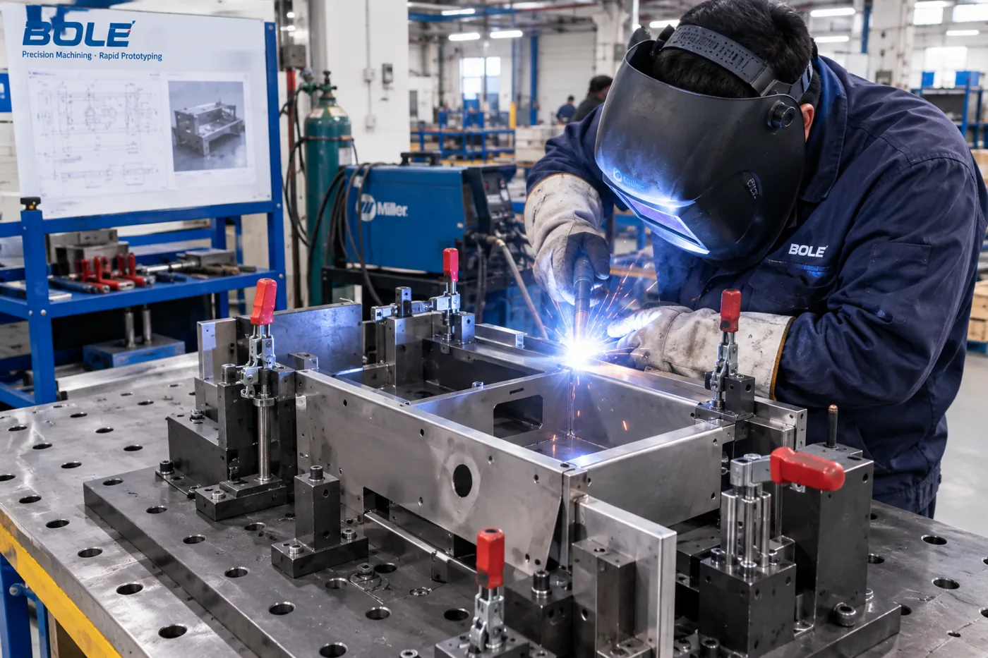
(4) Use Custom Welding Fixtures with Appropriate Locating and Restraint
For thin sheet metal with multiple welds, fixtures are essential for dimensional control. BOLE designs dedicated welding fixtures for precision sheet-metal products made in batches. Fixtures provide accurate locating datums and reliable support at multiple points, with appropriate clamping force. They prevent parts from shifting during welding without completely restraining thermal expansion, which could otherwise create excessive residual stress.
Practical production note: Do not use dimensions measured while the part is clamped as the final inspection standard. The true finished dimensions are those measured after the part is unclamped and spring-back has occurred as residual stress is released.
(5) Pre-deformation (Counter-deformation) Compensation
For products with stable, well-understood distortion patterns, BOLE may use pre-deformation: the part is pre-deformed in the opposite direction before welding, with an appropriate compensation value, so that the resulting welding shrinkage brings the part closer to its intended design dimensions.
Note: Compensation should not be estimated by intuition. It should be established using historical production data from similar products and confirmed through process trials. This method is not suitable for parts with complex structures or unstable distortion patterns.
(6) Control the Dimensional Chain Throughout the Manufacturing Process
Many welding deviations originate in upstream operations. BOLE establishes a comprehensive inspection system across the manufacturing process:
| Manufacturing Stage | Key Control Point |
|---|---|
| Drawing and tolerance review | Confirm critical dimensions, flatness, joint locations, and assembly-fit requirements before production. |
| Material and process confirmation | Verify the material grade, sheet thickness, welding method, and relevant quality requirements. |
| Cutting and bending control | Ensure parts meet dimensional-accuracy and geometric requirements before welding. |
| Fixture preparation | Check locating datums, clamping positions, and assembly alignment. |
| Welding process control | Use suitable welding parameters and follow the defined welding sequence. |
| Post-weld dimensional inspection | After unclamping and stabilization, inspect critical dimensions, flatness, angular accuracy, and assembly interfaces. |
| Correction when necessary | If distortion exceeds permitted tolerances, select an appropriate correction or rework method based on material properties, design, and quality requirements. |
(7) Post-Weld Inspection and Distortion Correction
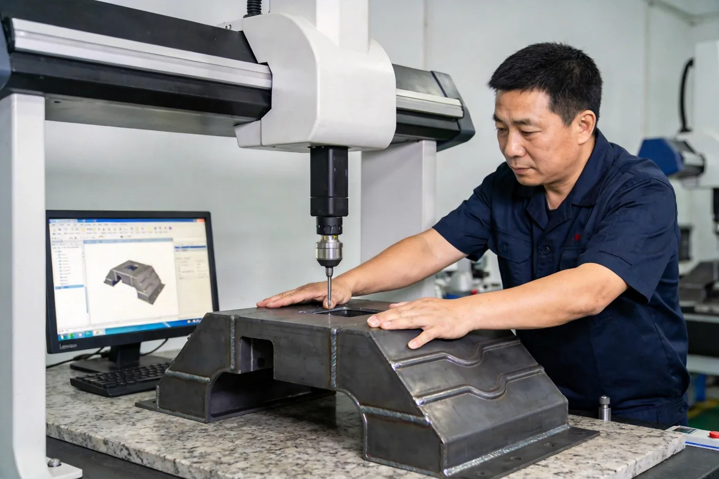
A good-looking weld does not guarantee dimensional compliance. Hole position deviations, flatness deviations, and angular deviations exceeding the specified tolerances may not be visible to the naked eye. Depending on the part’s tolerance class, BOLE uses calipers, height gauges, angle measuring gauges, inspection plates, coordinate measuring machines (CMMs), and dedicated gauges for inspection. Key inspection items are defined for precision sheet-metal parts, and inspection is performed after the part has been unclamped and its dimensions have stabilized.
If distortion exceeds the permitted tolerance, a correction method is selected according to the material properties. The correction process is tightly controlled to prevent cracks, surface damage, or degradation of part performance.
How Does BOLE Ensure the Quality of Welded Sheet-Metal Parts?
Controlling welding distortion is not a matter of correcting a single operation. It is a systematic effort covering drawing review, process planning, parameter selection, custom fixtures, in-process control, and final inspection. When BOLE receives a custom sheet-metal fabrication requirement, we first review the product’s application, material, dimensional tolerances, and assembly conditions to identify distortion risks early and recommend a suitable manufacturing process:
- Conduct a manufacturability review at the drawing stage and optimize joint design and weld layout to reduce distortion risk at the source.
- Select suitable welding parameters and control heat input appropriately.
- Provide custom welding fixtures for precision parts to ensure accurate positioning.
- Follow a standardized welding sequence.
- Inspect at each process stage; remove the fixture after welding before carrying out final dimensional verification.
- For high-precision sheet metal and thin-walled enclosures or frames, produce trial parts to validate the distortion-control plan before batch production.
Clear, complete engineering drawings and explicit tolerance and quality requirements are the foundation of custom sheet-metal manufacturing. BOLE provides one-stop manufacturing services for CNC machining, rapid prototyping, and custom sheet-metal fabrication, evaluating the most suitable process according to part geometry, material, and application.
Conclusão
The main causes of sheet-metal welding distortion are uneven thermal expansion and contraction, weld shrinkage, and the interaction between residual stresses and structural restraint. Thin sheets, long weld seams, asymmetrical weld layouts, and excessive heat input all increase the risk of distortion.
Controlling distortion requires more than post-weld correction. It calls for a comprehensive set of measures, including welding parameter optimization, welding sequence planning, joint and structural design optimization, fixture design, dimensional control throughout the manufacturing process, and post-weld inspection and correction.
Anticipating welding distortion during design and process planning can improve dimensional accuracy and consistency, reduce rework and scrap, maintain assembly fit and functionality, and enhance the overall quality of sheet-metal products.
Explore BOLE’s Sheet Metal Fabrication services ou send your drawings and project requirements for a manufacturing review.